Years ago when living near Binghamton New York I used to visit a junk yard on a fairly regular basis. They would take in lots of surplus stuff from some of the big manufacturers in the area including IBM, Singer-Link, General Electric, and Lockheed Martin. You could all kinds of funky stuff there and could often buy it for a song as long as the proprietor did not see any gold parts. Even a DB-25 connector with an angstrom of gold platting would boost your junk box from a five dollar purchase to 50. During one of those visits I found a large number (100+) of 24V military grade relay switches, a case of mil 4 position rotary switches, boxes and boxes of 1/4 watt resistors still on tape reels, and other stuff. Often I would be shocked at the price we citizens had paid for these parts only to have the contractor throw them away. Like that case of 144 4 position switches were $32 each. So now my garage is full of these priced items.
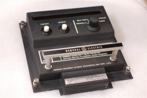
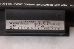
One item I have is rather interesting to me as an aviation buff. I have the front panel for a General Electric Pitch Augmentation Computer targeted for a Boeing aircraft. The GE part number is 89954-937E450G1 and the Boeing number is S241T400-102R. I shall attach a picture later after my camera changes back up again.
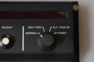
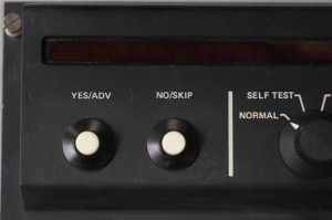
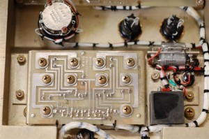
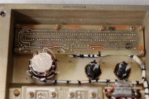
In any case this device has a 32 character long LED 5*7 font display, a power LED, two switches, and a rotary switch. Yes, its the same switch I have a case of. The inside is top quality. All boards are conformal coated, all harness are very neatly tied and routed. The parts all are mil grade and designed to take large shock and vibration. Circuit boards are all through hole (date code goes back to 1982) and supported with thermal and structural metal backer plates.
So just what I am going to do with this thing? Well the first project that comes to mind is a desk clock for work. I already have figured out how to drive the LED display and it is very doable from an Arduino. Add it a real time clock chip, interface to the existing switches, add a wall wart, and I should be good to go.
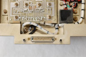
All the connections to this device are via a 33 pin Airborn WTB style connector. I have a request in for a mate to make the interface that much easier.
Since I only have the front panel, I was thinking about mounting it to a piece of Plexiglass to allow the curious to see the “tech porn” (shameless stolen from Dave Jones at EEVBLOG.COM) inside.
Overall unit
Function knob
Push buttons
Serial number plaque
Bottom circuit board are the 5 transistors for the column drives. To the right are power filters and transient voltage suppression. Above you can see the two switches, and the rotary switch.
Connector to rest of system
Top circuit board is the LED display using HP 4 character 5*7 font DIPS.
