After I have proven to myself that I have a good chance to get a solar compass to work for AVC, I started to look at improvements.
The first would have to be miniaturization. Currently the system is very bulky, finicky, and heavy. There is no way this would survive being mounted to an RC car.
Here are some current pictures of the setup:
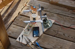
Close up of SUNDAR outside during testing.
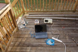
Full setup with SUNDAR, scope, and laptop
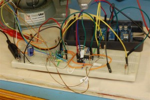
Amplifier board and Arduino. This takes the raw signal from the solar sensor and amplifies and biases it to get the best dynamic range from the Arduino’s ADC. A second chip on this board is a digital pot used to automatically adjust gain and bias.
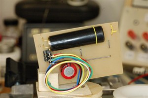
Closeup of the front on the sensor head. The black tube was to limit the field of view of the sensor. The red device is a supercap to keep power to the head should the slip ring break contact. Of the six rings, two were power, two ground, and two signal. You can also see the very simple elevation control to point the whole thing at the sun as it rises in the sky.
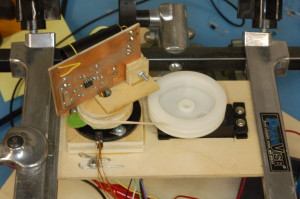
Overall view of the radar head. I am using a continuous rotation servo with a sailboat pulley on the output shaft. This drives the head via a rubber band on a wood pulley pressed to the nub on the slip rings. You can see the slip rings (black plastic) mounted to the left. The chip on the PCB is an opamp used convert the current based photo diode into a sufficient voltage to pass over the slip rings.
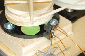
Close up of the photo interrupter sensor used as a sync pulse each time the radar head turns.
So the current implementation uses slip rings and a continuous rotation servo to rotate the sensor platform at a constant rate. I think I can simplify the whole system by changing from a radar to a tracker. I could put the sensor head on a stepper motor shaft and dither back and forth keeping the peak in the center. I would not only simplify the system, reduce the noise from the slip rings, and have a faster update rate. As such I just placed an order for a pretty small stepper and a controller from Pololu.
The second modification would be to improve the response of the sensor. Right now as the sensor swings by the sun, the pulse is nearly 50 degrees wide or +-25 of each side. That seems way too much. I tried to minimize the field of view of the sensor by putting a black tube on the front to act like blinders. But perhaps the plastic (the cover of a thin Sharpy marker) may be too reflective. I may try to roll a tube of black felt and try that.
