Sailboat start timer revisited

I have been stalled in my work on my robot. Current bug just seems insurmountable. I would come home and avoid the thing like the plague. So I decided to purposefully work on something else for a while. Continue reading

Posted in PIC, Sailboat Race Timer | Comments Off on Sailboat start timer revisited

Microscope (AmScope SM-3T)

My eyes are getting old. I can no longer focus on close items. For the last few years I used a magnification visor for close up work. But in recent time, even that is not good enough. To get close enough to solder tiny parts you set your face on fire with the soldering iron.

So, I took a deep breath and purchased a 3D microscope. I have used them for years at work and loved the ability to work for long times in relative comfort and with little eye strain. But $500 seemed like a bit much for a hobby.

But the way my eyes are, I can’t solder a 1/2 watt through hole resistor to a protoboard let alone a small SMT part. So I ordered an SM-3T from AmScope with 1/2x and 2x barlow lenses. I also got the 80 LED ring light. I did not order the video or camera options. I will wait a bit to get those.

It arrived and the unboxing went smooth. The only hiccup was their idiocy in requiring a password to download the user manual. They told me it was printed on the box, but after trying 10 different numbers I called them and gave them a piece of my mind. Would it have killed them to print a copy and include it in the box, or make it publicly available on the web?

So now I find I am spending all kinds of time in my lab looking at things. I find myself reverse engineering random PCBs because I can. I am sure the novelty will wear off in time.


Posted in AmScope | 3 Comments

Radio Shack is dead to me

I know it is not news, but Radio Shack is dead. My local store did not shutter when they went bankrupt. It has now been remodeled to bring in a cell phone store in a good 1/4 of the store. This has forced the store to drop merchandise. And what did they drop? Most of the hobbyist stuff.

What they dropped floors me. They no longer have project boxes, and prototype boards. But they do still have the rub on decals for etching your own circuit boards. What is the sense in that? Who ever was in charge of selecting merchandise for the hobby area obviously never held a soldering iron.

So my goal now, is to never step foot in the store. I will start to stock up on basic supplies from DigiKey and Mouser. Stuff like switches, a few transistors, and wire. I already have a start on being independent. It will not take much to divorce myself completely from them.

It is a sad day. I remember as a kid going to the store to browse the parts and imagine having the knowledge to use them. I then remember going to the store to buy parts I did know how to use. Now I go to the store, and wonder who might really be still using rub on stickers to make a PCB.

Posted in Personal | 1 Comment

Saleae Logic-8

I just was given a Saleae Logic-8 logic analyzer probe as a birthday gift. I am in love with not only the giver (my wife), but the unit itself. Admittedly I have only had it for an hour, but everything I have tested it against has worked nearly flawlessly. I did have one small hickup where the Windows client indicated some fault in downloading the data from the pod. But I only saw that once when I was screwing around with settings.

What came as a huge (pleasant) shock is that this is not just a logic analyzer with various protocol anayzers built in, but also a oscilloscope. Obviously this will not compete against a purpose made scope in features or specifications, but for a quick probe in the field it can’t be beat.

So far 3 thumbs up.

Posted in Product reviews | 2 Comments

First 3D printed part

My employeer has graciously allowed employees to use their top of the line 3D printer for personal projects subject to a bunch of conditions. My SUNDAR project falls within the guidlines for using minimal amount of materials and time. So for the last few months (work has been grueling) I have been working on designing the various parts I need for the sensor head.

I had some issues with finding a CADD program that would do the job. I have in fact tried 7 different programs and have rejected them all. The best of the lot so far is Cubify Invent, but even that I am not fully happy with. But with that aside, I did design a part and had it printed last night.

I am frankly amazed at the quality. Admitedly this is a huge industrial SLA machine and this part was run with the finest tip. Although not glass smooth, it came out very nicely. I will try to attach a picture soon.

Now I am off to design the rest of the parts and get them printed. What JOY!

Posted in Uncategorized | Comments Off on First 3D printed part

Dealing with angles (and averaging them)

The nasty thing about angle measurements is the fact that they roll over. That is to say if you add 10 degrees to 355 degrees you get 365, but what you really want is 5. So after every addition or subtraction you need to normalize the angle. By this I mean if the new angle is above 360.0, subtract 360 and if it less than 0.0 add 360.0.

If you are adding or subtracting one angle from another angle, then this pseudo code works:

if (ang > 360) {
  ang -= 360
} else if (ang < 0.0) {
  ang += 360
}

Of course if you want to use radians (and you should) then replace the 360.0 with 2*PI.

Now if you add up a bunch of angles, then the above code does not work. Assume you want 350+350+350. This gives you 1050. Normalize this with the above and you only subtract 360 from 1050 to get 690. This is still not a ‘legal angle’. You may be tempted to put the above pseudo code in a loop till such time as the angle is between 0 and 360, but from experience I would suggest against this. Years ago I did just this, but an error in the code caused the angle to approach infinity. What to guess how long it takes to normalize an absurdly large angle by iteratively subtracting 360 degrees at a time?

You may also be tempted to do some fancy modulo arithmetic to normalize the angle, but I also suggest against that. In the spirit of finding bugs as fast as possible, if you add 4 angles together, you should call the normalize routine 4 times (or pass in an argument for a fixed number of iterations). One the normalization is done, add an ASSERT to the code to check for 0-360.

Now the above assumed you were interested in angles in the range of 0 to 360. This is great for bearings and azimuths. But there are many other angles that are best measured in the range of -180 to +180. For these I have a different normalization routine. I have taken to calling the 0-360 angles Full Circle Angles (FCA) and the -180-+180 angles Half Circle Angles (HCA). Therefore I have an angles library that allows me to add subtract, and perform other operations on FCA, HCA, and a mixture of these angles.

In a previous post I mentioned the issue with averaging angles. Assuming the use of FCA angles, averaging an azimuth of 350 and 10 degrees does not yield the anticipated answer of 0 degrees but rather 180 (350+10)/2 = 180.

After a fair amount of Googling, I have found the answer to averaging. I should mention that there are in fact a gazillion ways to average based on your definition of what an average is for numbers that wrap around like angles. But using the definition of an average direction of motion, then the following works.

y = sin(a1) + sin(a2) + ... + sin(an)
x = cos(a1) + cos(a2) + ... + cos(an)
avg = atan2(y,x)

So a couple of caveats. Make sure you pass the right type of angles (deg/radians) into your trig functions. Second, look at the arguments to your atan2 function. They may be ordered (y,x) or (x,y).

So how does this work? Taking the sin of an angle and multiplying it by 1 gives the y component of a unit vector along your angle. The cosine gives you the x component. If you add up all the x and y values these give you the x and y magnitude of the sum of all the vectors. The resulting vector will be in the direction of the average. Now take the arctan of the x and y values and you get the resulting average heading.

Note that in some cases (such as in a complimentary filter) you may want to give unique weights to each angle. To do this, you can simply multiply the sines and cosines by the weight like this:

y = w1*sin(a1) + w2*sin(a2) + ... + wn*sin(an)
x = w1*cos(a1) + w2*cos(a2) + ... + wn*cos(an)
avg = atan2(y,x)

And that is how I deal with pesky angles!
Posted in Uncategorized | Comments Off on Dealing with angles (and averaging them)

On stepper motors

I have never designed a system with stepper motors in them, but I have used such systems in the past. After my first experiments with the SUNDAR, it became apparent that the best solution would be to replace the RC servor with a stepper. This I did using a small stepper and control board from Pololu. Both were simple to use and I had a somewhat working system in short order.

But it had warts. The motor did not seem to have much torque , and it would skip steps if I tried to make it spin faster than a crawl. I had been using full steps assuming I would get the fastest speed in this way, but it turns out the answer is more complicated. When using full steps, the coil current is either -100%, 0%, or 100%. Changing from one configuration to another is a large shock to the system. Its like getting hit with a hammer. The inertia of the rotor may prevent it from moving to the next step. But if you micro step, you are gradually ramping up one coil current as to decrease the other. The resulting torque is applied much smoother and the rotor can keep up.

So by decreasing the time between steps but using micro stepping I was able to at least double the motor speed without any lost steps. As a test, I ran the motor for one hour rotating a revolution one direction and then back the other. After the hour, the motor was still perfectly alignent. Now it is possible that I lost as many steps as I gained and had a zero sum gain, but I suspect that the motor simply did not miss any steps.

During this same test I also monitored the temperature of the motor. Rather surprisingly, the temperature went from ambient of 67F to about 130F! This is very different than a DC motor with little load. But a stepper always has the sum of its coils at 100% current and hence consuming 6 watts of power. 6 watts into a small chunk of metal will get hot. Consulting the datasheet the temperature rise was well within spec.

Since these initial tests, I have also done some mechanical work on the SUNDAR. I built a new platform to hold the motor and a new platform for the sensor. I am now working on a way to run the three needed wires from the base to the rotating sensor platform without getting tangled. I am also adding an optical beam break sensor to index the sensor platform on startup.

But at the same time, I am working with a group of elementary to middle school students on their FIRST LEGO League (FLL) research project. Been teaching them how to program Arduinos and the basics of electricity. Since they will be coming over to use my shop next weekend, I have been spending much of my time cleaning up to make room for them. Then the two weekends after that, I am a judge for FLL. Then after that we get close to Thanksgiving and after that Christmas. I do not see a way to get everything I need to complete done by June of next year for the 2014 AVC. Perhaps 2015?

Posted in Uncategorized | Comments Off on On stepper motors

Complimentary filter

I have been struggling with how to fuse all the data into one cohesive mess. In the case of heading I have several source. I have a magnetometer, the heading from GPS, the integrated value from the gyro, and if I can manage it, the solar compass.

They each have strengths and weaknesses. The magnetometer is great as long as the car is not moving, the servos moving, or it sitting on a man hole cover.

The GPS is great as long as the robot is moving a a reasonable speed and has a good lock.

The gyro has no ability to determine north, but for short periods of time can keep track of changes in heading.

The solar compass is fantastic as long as we have the sun and it is not too high in the sky.

So what is a poor robot to do? One solution is to use a Kalman filter to merge the data. But the math is complex and you need  mathematical model of your system to make best use of it. Now I have the habit of picking at everyone I know for knowledge (and even those I do not know). This has lead me to the complimentary filter.

The complimentary filter is nothing more than a weighted average. Rather than each heading having equal weight when taking an average, you assign each a unique weight. The more likely that the value is right the higher the weight you give it.

So how do you assign weights? The literature would have you use the parameter’s covariance. This is the inverse of the standard deviation. A parameter you have confidently measured would have a larger covariance than one you are not so sure about. There are lots of mathematical ways to determine covariance given sample sets of numbers. But in my case, I will take  simpler way out.

My weights will be the inverse of the expected accuracy of the system. Here are the cases:

GPS: Zero if velocity is under 2 meters/second, else it ramps up to 3 degrees at 6 m/s or above.

Magentometer: 5 degrees if motor is off, 180 degrees if on

SUNDAR: Based on the error it reports based on the signal to noise ratio

IMU: Starts with the accuracy of the device that last reset its heading. The accuracy then decreases by 90 degrees per minute before it gets reset by the best azimuth device.

My heading now becomes the weighted average using the equation:

heading = (h1*W1 + h2*W2 + h3*W3 + h4*W4)/(W1+W2+W3+W4)

The problem is this does not work for headings. To see why assume two equally weighted sensors providing the headings of 350 and 10 degrees. The average would be (350*1 + 10*1)/(1+1) or 180 degrees! Oops; wrong direction! We really should have gotten 0 or 360 degrees.

So how does one average headings? A future post will address that.

Posted in Uncategorized | Comments Off on Complimentary filter

SUNDAR light sensor experiment

I have been sidelined for a very long time due to work. I have only had a few days off from work in the last 2 months. Makes working on my AVC robot difficult if not impossible. But I have begun to work on my SUNDAR project a bit. I really need to know how strong an ND filter to put in front of my light sensor so that it can look straight into the sun without saturating the sensor.

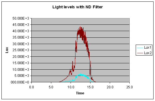
So I purchased two new sensors from AdaFruit. These are based on the GA1A12S202 chip from Sharp. I supplied them with 5V and digitized the data at 25Hz. The digital data I averaged over 4 seconds. I then delayed 26 seconds before doing it again. This gives me an averaged reading for each sensor every 30 seconds.

The first day the results looked like this: Lux

Both sensors show identical results and saturate during the day. The noisy data is from cloud cover.

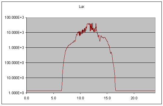
The second day I placed a single layer of an ND film over one of the sensors:

1ND

Although the voltage drop was not appreciably lower, it was enough to drastically lower the measured Lux. This is due to the logarithmic response (and not linear) of the sensor.

Although this would seem to have dropped the light intensity on the sensor into a good range, I am not convinced yet due to a few issues. The first is that the sensor was not perpendicular to the sun as it will be in the SUNDAR. Second there were two layers of glass between the sun and the sensors. Thirdly, the last two days have been not perfectly clear sky days. I will need to continue running this experiment for a few more weeks at least.

This experiment does have the advantage of proving that it gets lighter during the day and darker at night.

Posted in SUNDAR | Comments Off on SUNDAR light sensor experiment

Interesting bugs

Over the last few months, I have been sending to my software group at work a puzzle/quiz in the form of a bug I have found in my robot code. They seem to get a kick out of especialy since I offer a Peppermint Patty as a prize to the first right guess.

#1

Over the weekend I spend a few frustrating hours tracking down a bug in this seemingly simple idiot proof code. All it does is take the absolute value of a long integer (32 bits on an ARM processor). 

long labs(long val)
{
    long retval;
    if (val < 0)
    {
        retval = -val;
    } else {
        retval = val;
    }
    return retval;
}

So most of the time this code does exactly what you might expect. It returns the absolute value of the parameter you pass in. All except in one case. Can you figure it out?

#2

What does this code do and why do it this way?

uint32_t val;
val = (val << 3) + (val << 1);

#3

What is the next larger number greater than 8,388,608.0 when using an IEEE float. 

a)      8,388,608.002
b)      8,388,608.2
c)      8,388,609.0
d)      8,388,680.0

#4

Over the weekend I was working on a section of code that would increase then decrease the speed of my robot every 6 seconds to check the stability of my PID control loop. My task was running at 5Hz and each call to GetTimeInMilliseconds returned a number in the sequence 0, 200, 400, 600, … Needless to say I had a bug in this code as it did not change the speed at the desired rate. What did I do wrong?

    uint32_t systemTime;
    double   speedSP;

    /* Get the current time in milliseconds */
    systemTime = GetTimeInMilliseconds();

    /* Alternate between fast and slow every n seconds */
    if  ( (systemTime % 6*1000) == 0)
    {
      /* The error is not in this comparison as 4.0 is exactly represented as a float */
      if (speedSP == 4.0)
      {
        speedSP = 2.0; /* Set speed setpoint at 2 m/s */
      } else {
        speedSP = 4.0; /* Set speed setpoint at 4 m/s */
      }
    }


Posted in AVC, Personal, Software | 4 Comments